2-PIECE SYSTEM FOR DRIFT, DEFLECTION AND RIGID APPLICATIONS FOR CAST-IN-PLACE
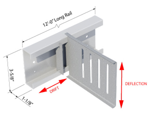
ClarkDietrich Drift Headed Rail (DHR-97) and Drift Clip 97 mil or 68mil (12ga or 14ga) is a uniquely designed two-piece system that is used to attach curtain-wall studs to the building structure and allows for vertical and lateral movement or to be rigidly attached.
To restrict clip lateral movement (Drift) along the Drift Rail, install one of two types of stops:
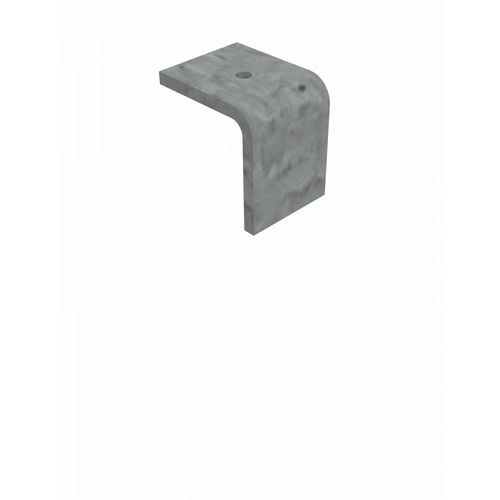
- Drift Locking Angle (DRLA) is an L-shaped clip
- Drift Locking Clip (DRLC) is a C-shaped clip
MATERIAL SPECIFICATIONS:
Yield Strength: 50ksi
Coating: G90
ASTM: A653/A1003
Drift Rail
Gauge: 12ga (97mil)
Design Thickness: 0.1017", Min. Thickness: 0.0966"
Drift Rail Clip
Gauge: 12ga (97mil)
Design Thickness: 0.1017", Min. Thickness: 0.0966"
Gauge: 14ga (68mil)
Design Thickness: 0.0713", Min. Thickness: 0.0677"
Nelson Headed Studs (DHR-97)
Headed Anchor Material: Grades 1010 through 1020, 51ksi (351MPa) minimum yield strength, 65ksi (448MPa) minimum tensile strength
Physical properties of Headed Anchors are in accordance with AWS D1.1.
Coating: G90 (Z275) hot-dipped galvanized coatin
PRODUCT DATA & ORDERING INFORMATION
Click the below Product Code to view Tech Datasheet
12GA CLIP / 12GA RAIL
| Product Code | Gauge | Mils | Clip Length | No. of slots per Clip |
No. of holes per Clip |
|---|---|---|---|---|---|
| DRC3-97 | 12 | 97 | 3.3875" | 2 | 4 |
| DRC6-97 | 12 | 97 | 5.875" | 4 | 8 |
| DRC8-97 | 12 | 97 | 7.325" | 4 | 8 |
14GA CLIP / 12GA RAIL
| Product Code | Gauge | Mils | Clip Length | No. of slots per Clip |
No. of holes per Clip |
|---|---|---|---|---|---|
| DRC3-68 | 14 | 68 | 3.3875" | 2 | 4 |
| DRC6-68 | 14 | 68 | 5.875" | 4 | 8 |
| DRC8-68 | 14 | 68 | 7.325" | 4 | 8 |
PACKAGING:
Drift Rail Clips: 25 Drift Clips per box. (Includes 55 OR 80 FastClip Deflection Screws per box.)
12' Drift Rail is individually packaged.
ALLOWABLE DRIFT HEADED RAIL AND CLIP LOADS BASED ON CAST-IN-PLACE TO THE STRUCTURE:
- Cast-in-Place / Embeddment of Rail by others
(Allowable loads based on stud connection only)
INSTALLATION:
Design load capacities for cast-in-place installations are tabulated in the product Design Guide and include:
With the Drift Headed Rail embedded in the concrete structure, the Drift Clips can be positioned as required:
- The framing stud web must contact the flat face of the long leg of the Drift Clip.
- Note that one of the four slots in the channel portion of the Drift Clip is longer than the others.
- Tilt the Drift Clip and position it so that the longer slot initially engages one leg of the Drift Rail.
- Rotate the Drift Clip to the vertical position, engaging all four slots with the Drift Rail legs.
Connection between the Drift Clip and Framing Studs:
- For bypass connections, Proprietary Deflection Screws are placed through each slotted hole of the long leg, of the Drift Clip to the web of the stud.
- The required number and location of the slotted holes used to secure the stud is determined by the required design load capacity.
- For rigid connections, self-drilling screws are placed through the pilot holes around the perimeter of the long leg of the Drift Clip to the web of the stud.
TO RESTRICT CLIP LATERAL MOVEMENT (DRIFT) ALONG THE DRIFT RAIL, INSTALL ONE OF TWO TYPES OF STOPS:
Drift Locking Angle (DRLA) is an L-shaped clip
- The long leg is inserted into the channel of the Drift Rail Clip, − The short leg is secured to the flange of the Drift Rail with a #10 self-drilling screw
Drift Locking Clip (DRLC) is a C-shaped clip
- The DRLC sits within the channel of the Drift Clip, and straddles the flanges of the Drift Rail.
- The two outside legs of the DRLC are secured to each flange of the Drift Rail with a #10 self-drilling screw.


